outside of the tyre and the pressure we read on the gauge when we pumped the tyre up. Unlike Gauge or Absolute pressure transmitters, Differential Pressure sensors are (a) Strain Gauge (b) Differential Capacitance (c) Vibrating wire.
Table of contents
- Purging the Sensing Lines of a Differential Pressure Transmitter | Brooks Instrument
- Read in Your Language
To calibrate an instrument involves checking that the output of the given instrument corresponds to given inputs at several points throughout the calibration range of the instrument. How to Calibrate Smart Transmitters. Record and put down the following can easily be sourced from transmitter nameplate: Connect all the equipment needed for the calibration exercise in the appropriate manner.
Then connect them according to your connection diagram. A typical DP cell transmitter calibration diagram is shown below:.
- dating site call tag?
- zooey deschanel dating history?
- friendship dating questions?
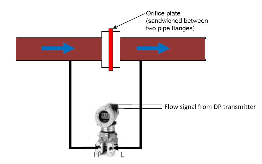
- Applications of DP transmitters ~ Learning Instrumentation And Control Engineering.
- best dating site to meet doctors?
- dating a christian man with a past?
- Condensate Pot for Pressure Transmitters.
For your application, this could be modified slightly. For example if the pressure source is a hand pump, you can easily control the pressure applied to the DP cell. However, if you are doing field calibration that requires the use of the actual process pressure, you will need a pressure regulator in conjunction with a pneumatic calibrator to help you control the pressure applied to the DP cell.
Most transmitter calibration done is a five point calibration. The graph below illustrates the correlation between input and output values. Readings are taken for both increasing and decreasing input values and the corresponding transmitter output values are recorded Step 5: In most calibration done, you will be doing either a bench shop calibration — A bench calibration is a procedure where the device is calibrated at a calibration bench using calibration devices to simulate the process, — or a field calibration where the actual process is used.
In one other project, the client required pot for high pressure 50bar and above and medium pressure 6bar to 50bar steam but not for low pressure steam.
In this case I think pot was used only for safety purposes, where during commissioning you fill it with water before actually opening the isolation valve on your steam line whereby thermal shock is eliminated in the pressure cells in you PTs'. Just for information the following installation standard can be used for steam flow applications as well, there is no need for these catch pots either in flow applications.
The impulse line can serve the same purpose as a catch pot so no need to use the catch pots on a steam pressure or flow installation. The only difference is that the transmitter will be a bit further away from the tapping point without a catch pot in the installation. Think in terms of volume of liquid between the tapping point and the transmitter and you will see there is no difference if you just make the impulse lines a bit longer.
The impulse line only design, will actually cool the condensed steam faster per meter than the pots due to overall volume per surface area contact with the cooler environment. The tapping point should be made to the side 10 or 2 o'clock or preferably the top upper quadrant - 12 o'clock of the process line, and fitted with a suitable rated process isolation valve.
The pressure transmitter should be positioned well below the tapping point so that the impulse line will stay filled with condensate while in service same as wet-leg in a steam drum level application. A T-Piece must be installed at the bend in the impulse line before it goes down to the transmitter for the purpose of filling. The distance of the impulse line from the tapping point down to the transmitter should be chosen to ensure that adequate cooling occurs to prevent thermal damage to the transducer.
Purging the Sensing Lines of a Differential Pressure Transmitter | Brooks Instrument
Transmitter temperature rating as well as steam possible max temperatures needs to be considered to calculate the length and not just the "rule of thumb". The impulse line MUST be filled with ambient temp water prior to start-up putting transmitter online for the first time to prevent possible thermal damage to the transducer by the live steam. The original idea if the catch pot, a million years ago, in steam level, flow and pressure applications was to form a thermal buffer between the steam and the transmitter and to keep the impulse line to the transmitter filled to exactly the same level all the time.
The T-Piece fitting instead of a catch pot, can do exactly the same job.
Read in Your Language
All you need to do is install the transmitter in some applications a bit lower down or further away from the tapping points. The overall effect is exactly the same in level, flow and pressure steam installations.
- Useful Engineering Links.
- Useful Engineering Links.
- tom pandolfo dating?
- goth dating site uk?
- Instrument Hook-up Drawing | glohi.xsrv.jp.
I am battling with the installation of steam flow meter. The manufacturer is confusing me. Initially the condensate pot was below steam line. But after amendment it stop reading. I checked the DPT. I am completely screwed over. My boss is quarreling with me. The idea is to - have two condensate pots, one for each impulse leg, at exactly the same elevation. Read Sam's post above, and look at a couple of these graphic illustrations to get an idea of what the seal pots should be doing.
This one shows the contents of the condensate pot: This one shows the Filling Tees that do the same thing as a condensate pot, that Sam is talking about, on a horizontal steam pipe: Similar to the one above, but for a vertical steam pipe: This one shows close coupled filling Tees above the horizontal steam pipe http: This one shows older style piping with horizontal condensate pots: In my experience there is no technical problem if you install the pressure transmitter without a condensate pot as long as you keep sufficient impulse tube length for the cooling down of the temperature.
However, use of condensate pot has some advantages. It allows steam line to be short and most part of the impulse tube handling liquid only thus reducing the chance of leakage. Also condensate pot allows for easy start up without waiting for steam to cool down. But for DP flow measurement application condensate pot is a must.
Not only that condensate pot location is also vital. The main technical reason is to avoid the unequal condensation between two lines. Otherwise you will get wrong DP and wrong flow measurement. My personal experience in one project I have seen the flow signal to be oscillating continuously. You have clicked on the "? To search the site, enter your search terms in the box labeled "search the site" and hit Enter.